
Page 8 - KS_materijal za vezbe_2015
P. 8
Specific rules for design and detailing of concrete buildings. Design for DCM and DC. Illustration of elements...
M.N. Fardis and G. Tsionis
D C B A
SCHEMATIC SECTION
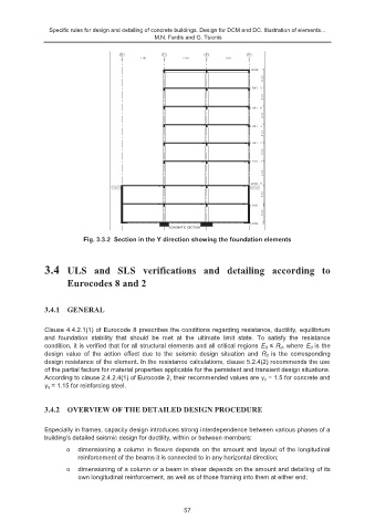
Fig. 3.3.2 Section in the Y direction showing the foundation elements
3.4 ULS and SLS verifications and detailing according to
Eurocodes 8 and 2
3.4.1 GENERAL
Clause 4.4.2.1(1) of Eurocode 8 prescribes the conditions regarding resistance, ductility, equilibrium
and foundation stability that should be met at the ultimate limit state. To satisfy the resistance
condition, it is verified that for all structural elements and all critical regions E d ≤ R d , where E d is the
design value of the action effect due to the seismic design situation and R d is the corresponding
design resistance of the element. In the resistance calculations, clause 5.2.4(2) recommends the use
of the partial factors for material properties applicable for the persistent and transient design situations.
According to clause 2.4.2.4(1) of Eurocode 2, their recommended values are γ c = 1.5 for concrete and
γ s = 1.15 for reinforcing steel.
3.4.2 OVERVIEW OF THE DETAILED DESIGN PROCEDURE
Especially in frames, capacity design introduces strong interdependence between various phases of a
building’s detailed seismic design for ductility, within or between members:
o dimensioning a column in flexure depends on the amount and layout of the longitudinal
reinforcement of the beams it is connected to in any horizontal direction;
o dimensioning of a column or a beam in shear depends on the amount and detailing of its
own longitudinal reinforcement, as well as of those framing into them at either end;
57