
Page 4 - KS_materijal za vezbe_2015
P. 4
Introduction to the RC building example. Modeling and analysis of the design example.
P. Fajfar and M. Kreslin
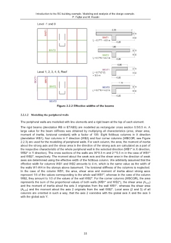
Figure 2.2.2 Effective widths of the beams
2.2.1.2 Modelling the peripheral walls
The peripheral walls are modelled with line elements and a rigid beam at the top of each element.
The rigid beams (denotation RB in ETABS) are modelled as rectangular cross section 0.5/0.5 m. A
large value for the beam stiffness was obtained by multiplying all characteristics (area, shear area,
moment of inertia, torsional constant) with a factor of 100. Eight fictitious columns in X direction
(denotation WB1), four columns in Y direction (WB2) and four corner columns (WBCOR, see Figure
2.2.3) are used for the modelling of peripheral walls. For each column, the area, the moment of inertia
about the strong axis and the shear area in the direction of the strong axis are calculated as a part of
the respective characteristic of the whole peripheral wall in the selected direction (WB1* in X direction,
WB2* in Y direction). The cross sections of the walls are 30*0.3 m and 21*0.3 m in the case of WB1*
and WB2*, respectively. The moment about the weak axis and the shear area in the direction of weak
axes are determined using the effective width of the fictitious column. We arbitrarily assumed that the
effective width for columns WB1 and WB2 amounts to 4 m, which is the same value as the width of
the walls W1-W4 in the storeys above basement. The torsional stiffness of the columns is neglected.
In the case of the column WB1, the area, shear area and moment of inertia about strong axes
represent 1/5 of the values corresponding to the whole wall WB1*, whereas in the case of the column
WB2, they amount to 1/3 of the values of the wall WB2*. For the corner columns (WBCOR), the area
represents the sum of the proportional values of both walls (WB1* and WB2*), the shear area (A s,22 )
and the moment of inertia about the axis 3 originates from the wall WB1*, whereas the shear area
(A s,33 ) and the moment about the axis 2 originate from the wall WB2*. Local axes (2 and 3) of all
columns are oriented in such a way, that the axis 2 coincides with the global axis X and the axis 3
with the global axis Y.
33