
Page 7 - KS_materijal za vezbe_2015
P. 7
Specific rules for design and detailing of concrete buildings. Design for DCM and DC. Illustration of elements...
M.N. Fardis and G. Tsionis
3.3 Geometry of foundation elements
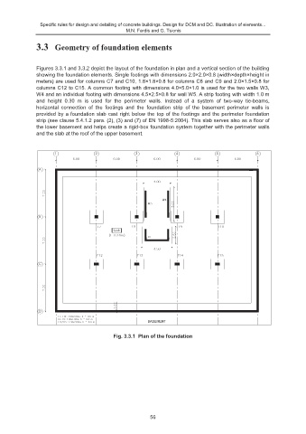
Figures 3.3.1 and 3.3.2 depict the layout of the foundation in plan and a vertical section of the building
showing the foundation elements. Single footings with dimensions 2.0×2.0×0.8 (width×depth×height in
meters) are used for columns C7 and C10, 1.8×1.8×0.8 for columns C8 and C9 and 2.0×1.5×0.8 for
columns C12 to C15. A common footing with dimensions 4.0×5.0×1.0 is used for the two walls W3,
W4 and an individual footing with dimensions 4.5×2.5×0.8 for wall W5. A strip footing with width 1.0 m
and height 0.30 m is used for the perimeter walls. Instead of a system of two-way tie-beams,
horizontal connection of the footings and the foundation strip of the basement perimeter walls is
provided by a foundation slab cast right below the top of the footings and the perimeter foundation
strip (see clause 5.4.1.2 para. (2), (3) and (7) of EN 1998-5:2004). This slab serves also as a floor of
the lower basement and helps create a rigid-box foundation system together with the perimeter walls
and the slab at the roof of the upper basement.
1 2 3 4 5 6
A
B
SLAB
C
D
BASEMENT
Fig. 3.3.1 Plan of the foundation
56